A usable, homemade weather station
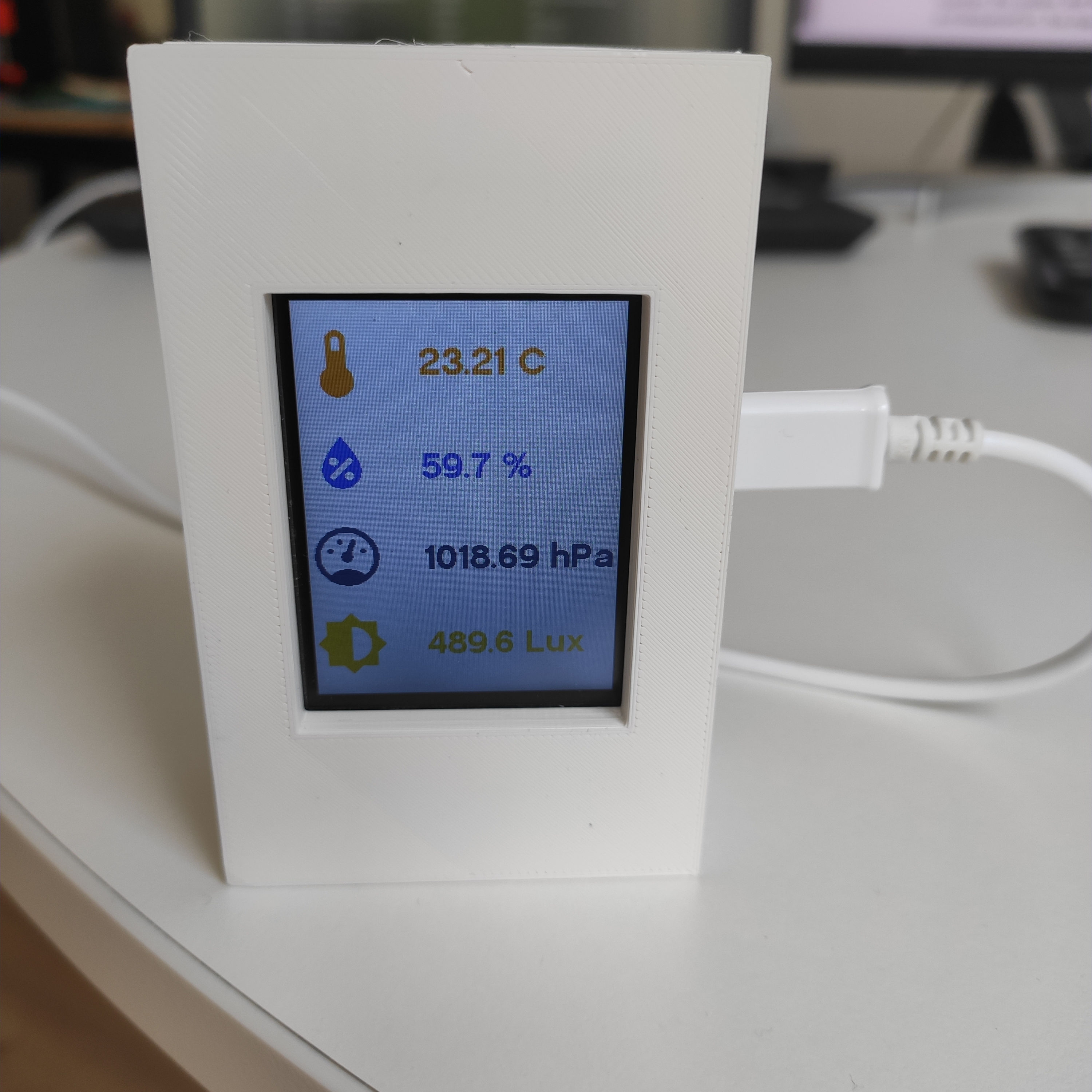
In this article I will detail how I built a simple weather station from scratch. This station measures the humidity, temperature, pressure and luminosity inside my flat and displays them on a small screen. It also sends these measurements to a MQTT server via wifi. I can then access all these metrics from my Home Assistant server. The station is powered with a micro-USB cable.
Background
I’ve been playing with microelectronics for a while, but recently I decided to push a project until the very end. I decided to make a mini weather station “from scratch”. We could argue on what “from scratch” means, but since I’m a beginner with microelectronics, I allowed myself to use a pre assembled ESP32 dev kit board, and sensors mounted on breakout boards. Everything was soldered on a perfboard. I designed and 3D printed the enclosure.
There was probably much better ways to build this weather station. Please feel free to contact me to tell me how I could have built it better. I just wanted to get it to work, even if it’s not perfect (and preferably without burning down my house).
Components
Here are the components I used:
- Light sensor
- Temperature, pressure, humidity sensor
- TFT screen
- ESP32 dev kit board
- 5x7 cm perfboard
The ESP32 dev kit is the main component of the circuitry: it has wifi (and bluetooth) capabilities and it will perform all the logic of the weather station. It will trigger measurements from the sensors, wake up the screen, send the data to the MQTT server, etc. The two sensors I used are I2C sensors.
Wiring
I failed several times while mounting all the components on the perfboard. It needed to meet the following criteria:
- The assembly needed to take as little space as possible
- The light sensor needed to be located at the top of the assembly (to properly measure the ambiant light)
- The temperature sensor needed to be as far away as possible from the main board (the main board heats up when wifi is ON)
- The TFT screen is mounted on the front face of the enclosure, but is connected on the perfboard. The tension on the wires needed to be minimal.
- The micro USB port of the ESP32 needed to be available, to power the station
Ultimately I ended up with the (ugly) assembly below:
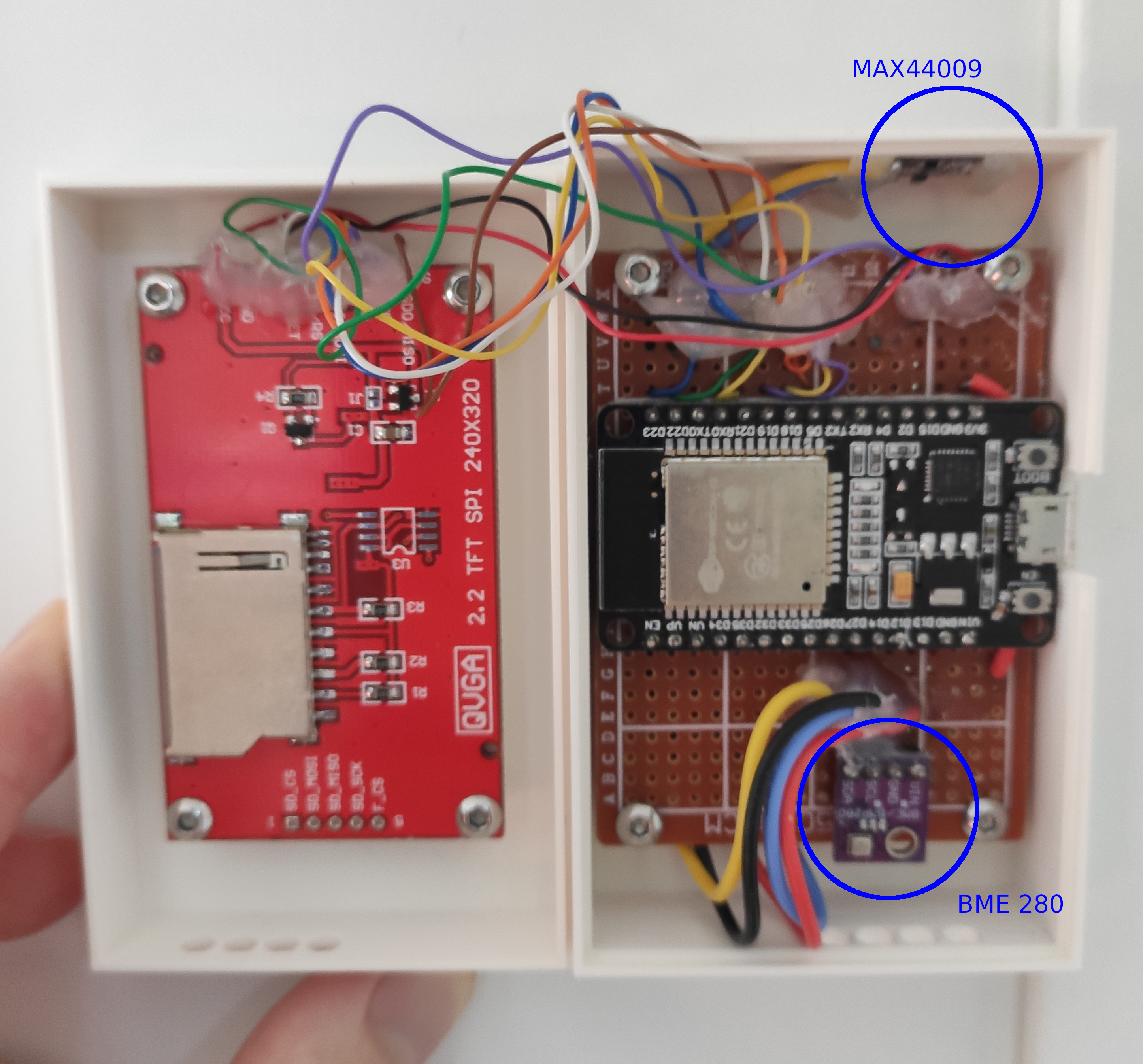
I used some hot glue to relieve the tension on the wires at the soldering points. Without this the wires would often break, making manipulation of the whole assembly tedious. It’s not pretty, and from what I read the hot glue might start detaching in a few months, but for now the whole thing is robust enough.
Design of the enclosure
I wanted to use a FOSS software to design the enclosure so I used FreeCAD. It doesn’t really compare to Onshape or SolidWorks (yet?) but it was good enough for the job, especially since the design of the enclosure was quite simple.
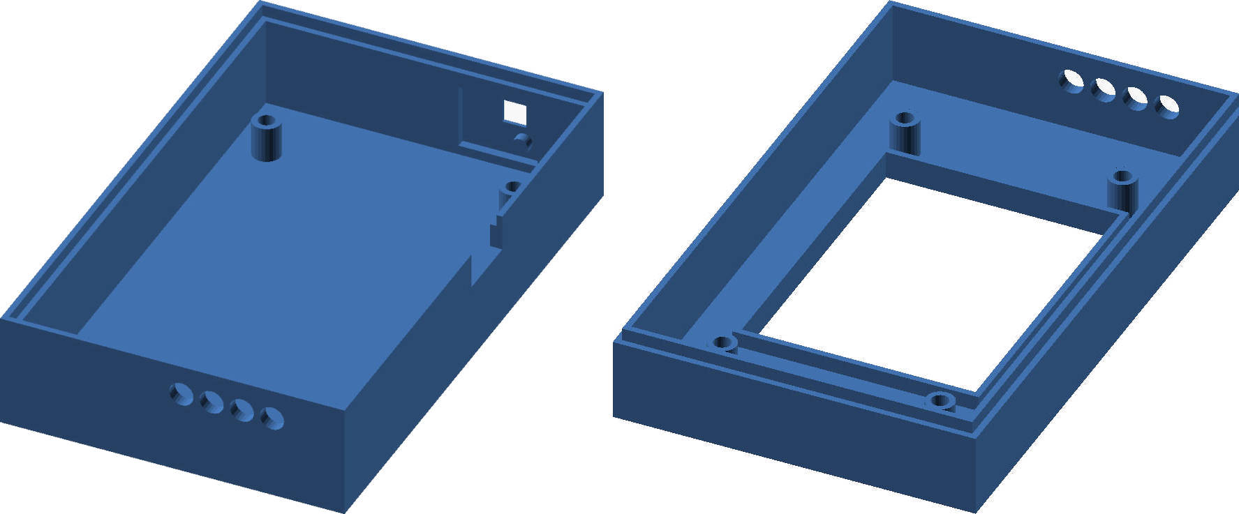
You can find the FreeCAD files here: front; back
And the STL files (for 3D printing) are here: front; back
It took me 4-5 iterations to get the sensors perfectly aligned with the openings on the sides of the enclosure.
Code and routers
I used Micropython to implement all the logic. I use Python every day at work and it was simply the best choice to get this project done. Of course this was only possible because the ESP32 is really a beast (compared to an Arduino UNO for example). Micropython requires 256Kb of RAM to run. The ESP32 has 520 KB of SRAM. In comparison, an Arduino UNO only has 2 KB.
You can find the full code here: https://github.com/JPFrancoia/esp32_devkit_weather_station
Implementing the logic of the weather station seemed simple at first, but I had a lot of reliability issues:
- Sometimes the hardware (e.g: the sensors) wouldn’t answer, because of a faulty wiring or because the measurement frequency was too high
- Sometimes the station couldn’t connect to the network
- Sometimes the messages sent to the MQTT server would never arrive
Solving the hardware issues was straightforward: better soldering of the components and less frequent measurements. Solving the network issues proved to be harder. It turns out the wifi antenna on this kind of board isn’t really good (for a board costing less than 10€, no surprise…). So instead of letting the station communicate directly with my main router (which is far away from the final position of the weather station), I turned a Raspberry pi 4 that I had in a drawer into a network bridge. The Pi acts like a relay, and I positioned it close to the station. To do that I plugged a wifi dongle into the Pi to give it an additional wifi interface (the Raspberry pi models 3 and 4 already have an internal wifi chip). Then I created a small network on one wifi interface so that the weather station could communicate with the Pi. This small network is isolated from the Internet. The station sends its data to the Pi via this small network, but the Pi is connected directly to my main router via its other wifi interface (coming from its internal wifi chip).
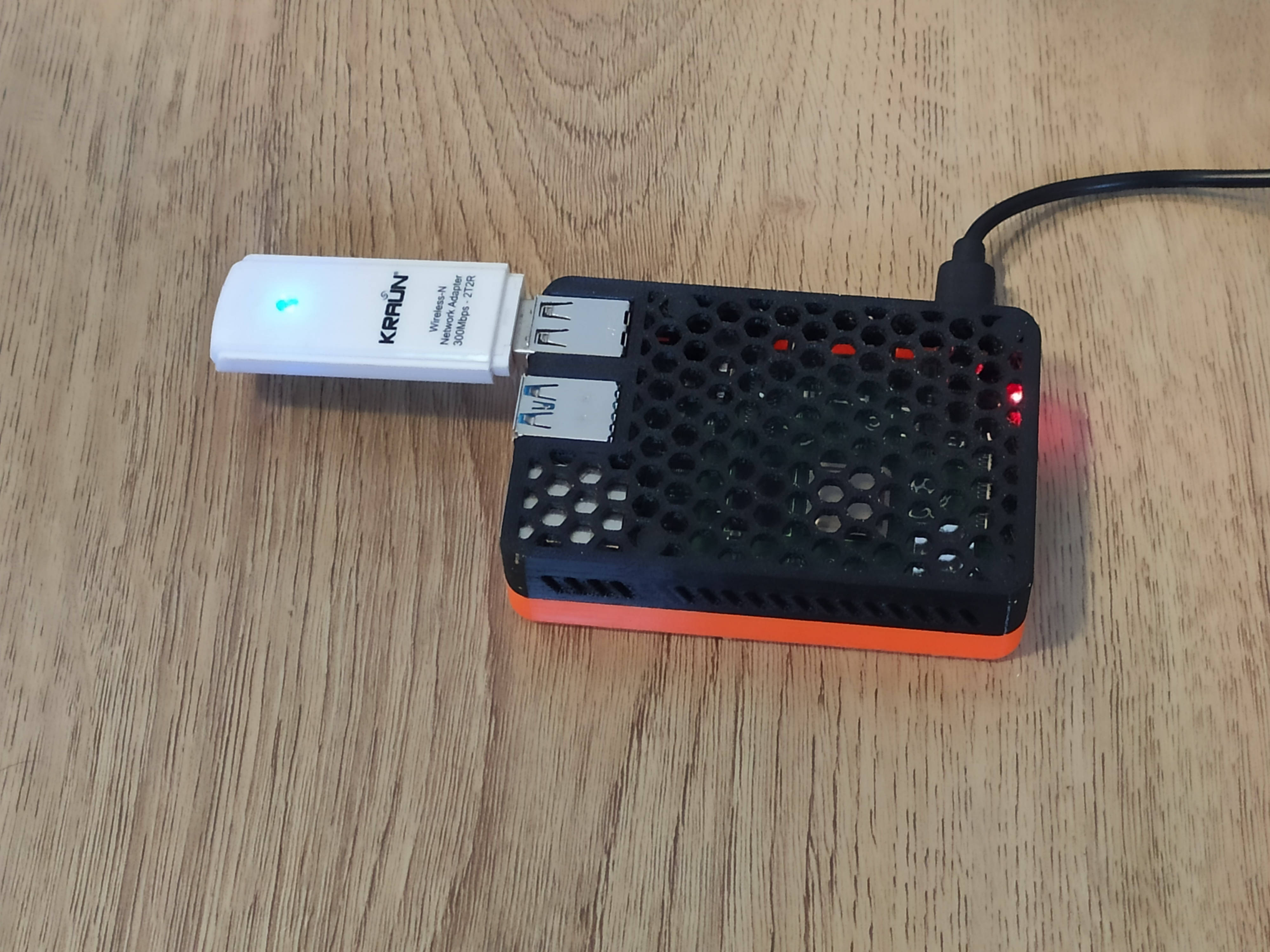
The MQTT server lives on the Raspberry Pi, as well as the Home Assistant server. Ultimately, the Pi acts as a node: sensors on the small wifi network can send data to it, and I can connect to the Pi via my main wifi network, to access the Home assistant server and see the measurements:

What I tried but didn’t work
At first I wanted to display the information sent by the sensors on an e-ink screen. I was able to display some numbers on the screen, but the e-ink screen drivers weren’t well supported and I couldn’t get the screen to work reliably. This is a shame because this kind of screen doesn’t need a backlight to be read, while a TFT screen does. But the TFT screen is half the price.
